- Authors

- Name
- Desi Ilieva
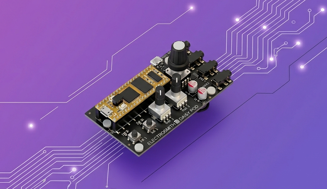
The Daisy Pod is a compact audio development board from Electro-Smith. It has a Daisy Seed at its core, two knobs, two buttons, and stereo audio I/O already wired up. It's a good starting point for hardware DSP because there's barely any setup — you write code and sound comes out.
Introduction
This tutorial walks through building a simple multi-waveform oscillator on the Daisy Pod. The end result is a synthesizer that:
- outputs a continuous tone to the stereo line out
- lets you control pitch and volume via the two knobs
- lets you cycle through sine, square, and triangle waveforms with a button
- has a mute toggle on the other button
- lights the onboard LED when either button is held
It's a small project but it touches all the fundamentals — audio callbacks, ADC reading, button debouncing, and the DaisySP oscillator. Everything else you'd want to build on the Pod extends from exactly this structure.
The full source is available at github.com/d3ssy23/DaisyProjects-MultipleWaveforms.
- What You Need
- Project Setup
- The Makefile
- Code Walkthrough
- The Audio Callback
- The Main Loop
- Building and Flashing
- What the Controls Do
- Summary
What You Need
- Daisy Pod (or Daisy Seed with the Pod carrier board)
- USB-C cable
libDaisyandDaisySPcloned locally — both are from Electro-Smith's GitHubarm-none-eabi-gcctoolchain installeddfu-utilfor flashing over USB
If you haven't set up the toolchain before, the Daisy wiki covers the environment setup for Mac, Linux, and Windows.
Project Setup
The project is a single .cpp file plus a Makefile. No CMake, no IDE project files needed. The structure is:
MultipleWaveforms/
├── MultipleWaveforms.cpp
├── Makefile
└── build/           ← generated on first make
Clone the repo or just create the two files yourself — the Makefile is the same for any Daisy Seed project.
The Makefile
TARGET = MultipleWaveforms
CPP_SOURCES = MultipleWaveforms.cpp

LIBDAISY_DIR = ../../DaisyExamples/libDaisy
DAISYSP_DIR  = ../../DaisyExamples/DaisySP

SYSTEM_FILES_DIR = $(LIBDAISY_DIR)/core
include $(SYSTEM_FILES_DIR)/Makefile
The paths LIBDAISY_DIR and DAISYSP_DIR point to where you cloned the two libraries. Adjust them to match your local directory structure — this is the only thing you'd need to change if you clone the repo.
libDaisy is the hardware abstraction layer — it handles the audio engine, ADC, GPIO, and all the Seed peripherals. DaisySP is the DSP library on top of it — it has the Oscillator class we're using here, plus filters, envelopes, effects, and more.
Code Walkthrough
At the top of the file:
#include "daisy_seed.h"
#include "daisysp.h"

using namespace daisy;
using namespace daisysp;
daisy_seed.h pulls in the hardware layer. daisysp.h pulls in the DSP classes. The using namespace declarations just keep the code shorter — without them you'd write daisy::DaisySeed and daisysp::Oscillator everywhere.
Then the globals:
DaisySeed hw;
Oscillator osc;
Switch button1, button2;

float knob_value_amp, knob_value_freq;
bool is_muted = false;
DaisySeed hw is the hardware object — everything goes through it. Oscillator osc is the DaisySP oscillator. Switch is the debounced button class from libDaisy. The two floats store the latest knob readings, and is_muted tracks the mute state.
These are globals because the audio callback needs access to them. In embedded audio you can't pass data through function arguments across the callback boundary in the usual way, so shared globals (or a context struct) are standard practice here.
The Audio Callback
void AudioCallback(float *in, float *out, size_t size)
{
    for(size_t i = 0; i < size; i += 2)
    {
        if(!is_muted)
        {
            float sig = osc.Process();
            out[i]   = sig; // left
            out[i+1] = sig; // right
        }
        else
        {
            out[i]   = 0.0f;
            out[i+1] = 0.0f;
        }
    }
}
This is where audio happens. The Daisy audio engine calls this function in real time at the configured block size. out is the interleaved stereo output buffer — i is the left channel sample, i+1 is right.
osc.Process() advances the oscillator by one sample and returns the current output value as a float between -1.0 and 1.0. We write the same value to both channels for mono output on a stereo line.
When muted, we write zeros. That's all muting is at this level — output silence.
Note that i += 2 — the buffer is interleaved, so every pair of floats is one stereo frame. If you increment by 1 instead you'd be writing to the wrong channels on every other frame.
The Main Loop
The main() function sets everything up and then runs forever:
int main(void)
{
    hw.Configure();
    hw.Init();

    osc.Init(hw.AudioSampleRate());
    osc.SetFreq(440.0f);
    osc.SetWaveform(Oscillator::WAVE_SIN);
hw.Configure() and hw.Init() boot the hardware. osc.Init() takes the sample rate from the hardware object so the oscillator knows what rate it's running at — this matters for the internal phase accumulator. We start at 440 Hz (A4) with a sine wave.
    AdcChannelConfig adc_cfg[2];
    adc_cfg[0].InitSingle(hw.GetPin(15)); // amplitude knob
    adc_cfg[1].InitSingle(hw.GetPin(21)); // frequency knob

    hw.adc.Init(adc_cfg, 2);
    hw.adc.Start();
The ADC needs to be configured before use. We create two channel configs, assign them to the physical pins the Pod's knobs are wired to (15 and 21), initialize the ADC with both configs, and start it. After this, hw.adc.GetFloat(0) and GetFloat(1) return the current knob values as floats between 0.0 and 1.0.
    button1.Init(hw.GetPin(28), 100);
    button2.Init(hw.GetPin(27), 100);
The second argument to Init is the debounce time in milliseconds. 100 ms is conservative — buttons are noisy at the hardware level and without debouncing you'd get multiple triggers per press. The Switch class handles this automatically once you call .Debounce() in the loop.
hw.StartAudio(AudioHandle::InterleavingAudioCallback(AudioCallback));
This starts the audio engine. From here on, AudioCallback is being called repeatedly in the background on its own interrupt. The main loop just handles controls.
    for(;;)
    {
        button1.Debounce();
        button2.Debounce();

        hw.SetLed(button1.Pressed() || button2.Pressed());

        knob_value_amp  = hw.adc.GetFloat(0);
        knob_value_freq = hw.adc.GetFloat(1);

        osc.SetAmp(knob_value_amp);
        osc.SetFreq(knob_value_freq * 1000.0f + 100.0f);
.Debounce() needs to be called once per loop iteration to update the button state. Without it, .RisingEdge() won't work correctly.
knob_value_freq * 1000.0f + 100.0f maps the 0.0–1.0 knob range to 100–1100 Hz. That gives you roughly two octaves of range, from a low bass tone up to a high but still audible frequency. You can adjust the multiplier and offset to change the range.
        if(button1.RisingEdge())
        {
            is_muted = !is_muted;
        }
.RisingEdge() returns true only on the first frame where the button transitions from not-pressed to pressed. It won't keep firing while the button is held. This is what you want for a toggle — press once to mute, press again to unmute.
        if(button2.RisingEdge())
        {
            static int waveform = 0;
            waveform = (waveform + 1) % 3;

            switch(waveform)
            {
                case 0: osc.SetWaveform(Oscillator::WAVE_SIN);    break;
                case 1: osc.SetWaveform(Oscillator::WAVE_SQUARE); break;
                case 2: osc.SetWaveform(Oscillator::WAVE_TRI);    break;
            }
        }

        System::Delay(1);
        __WFI();
    }
}
The static int waveform inside the if block persists between calls — it's local but not re-initialized every time the condition is entered. We increment it and wrap with % 3 to cycle through the three waveforms.
__WFI() is "Wait For Interrupt" — a low-power instruction that pauses the CPU until the next interrupt fires (which will be the audio callback or the 1 ms System::Delay timer). It just keeps the main loop from burning CPU doing nothing.
Building and Flashing
Get the Pod into bootloader mode: hold the Boot button, press and release Reset, then release Boot. The LED should be solid.
Then from the project directory:
make
make program-dfu
make compiles and links everything into a .bin and .elf in the build/ folder. make program-dfu erases the flash and loads the new binary over USB using dfu-util. Once it finishes, the Pod reboots and starts running the code.
If dfu-util can't find the device, make sure it's actually in bootloader mode and that you have the USB permissions set correctly on Linux (udev rules for the STM32 DFU device).
What the Controls Do
| Control | Pin | Function |
|---|---|---|
| Knob 1 | 15 | Amplitude (0.0 – 1.0) |
| Knob 2 | 21 | Frequency (100 – 1100 Hz) |
| Button 1 | 28 | Toggle mute |
| Button 2 | 27 | Cycle waveform (sine → square → triangle) |
| LED | — | On while either button is held |
The audio comes out of the Pod's stereo line out — the same signal on both channels, so it's effectively mono on a stereo output. Plug into monitors or headphones and both sides will be identical.
Summary
This project covers the core structure of any Daisy Pod audio application:
hw.Configure()+hw.Init()boots the hardwareosc.Init(hw.AudioSampleRate())initializes a DaisySP oscillator at the correct sample rateAdcChannelConfig+hw.adc.Init()+hw.adc.Start()gets the knobs readingSwitch.Init()with a debounce time gets buttons working correctlyhw.StartAudio()starts the audio engine and hands control to the callback- The audio callback runs on interrupt —
osc.Process()per sample, interleaved stereo output atiandi+1 - The main loop reads controls, updates oscillator parameters, and uses
.RisingEdge()for one-shot button events make+make program-dfuwith the Pod in bootloader mode flashes the binary over USB
From here you could add an envelope triggered by a button, a second oscillator for detuned unison, or a simple LFO modulating the frequency. The structure stays the same — audio callback handles signal generation, main loop handles control reading and state changes.